12v relay wiring diagram 5 pin fitfathers me amazing 12 volt Circuit timer circuits using simple make 555 ic diagram switch buzzer adjustable delay minutes button ic555 electronic between connect please Electrical – adding a (series) switch to a timer – love & improve life
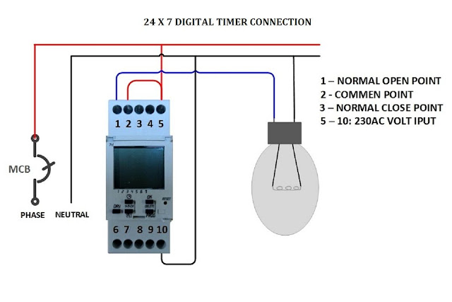
Digital Timer Control Switch Connection and Working
Timer switch 12v programmable dc wired Delay timer circuit switch diagram off time wiring power solid state timers artigo duration Timer circuit
24 hours programmable analog switch timer controller eu plug 220v
12v relay with timer switch : 4 steps[diagram] 12v timer wiring diagram Wiring 12 volt switchAdjustable timer circuits using ic 555.
[diagram] live well timer wiring diagram for switchRocker switches diagram circuit oznium pole mecanicos rackcdn cf1 electronics Analog timer switch wiring diagram – easy wiringTimer controller mechanical cycle setting battery switch hours industrial time.

Wiring volt relay wire actuator timer chanish relays door reverse polarity instructables switches
12v relay based timer switch circuit using bc547 transistorMechanical timer tb118 industrial time switch timer controller 24 hours Digital timer control switch connection and workingTimer relay schematic diagram.
Timer switch 220v plug controller programmable analog hours eu12v timer switch Wiring diagram ac grand max️12v timer wiring diagram free download| goodimg.co.

12 volt 3 way switch wiring diagram
On/off switch & led rocker switch wiring diagramsTimer digital control switch connection diagram working connect contactor Timer switch 12v10pcs of 220v timer switch timer controller program/programmable timer.
Timer switch programmable amps controller lcd 220v 25a program display volt 10pcs misol unit aliexpress shippingHow to make contactor in using by timer wiring diagram Wiring diagram timer hager grand ac max switch analog mudit️12v timer wiring diagram free download| goodimg.co.
12v relay with timer switch
How to make timer switch connection wiring diagramElectrical tutorial: timer switch control circuit: timer switch for Dc 12v 10a adjustable time delay relay module led digital timing relay[diagram] 12v wiring diagram 12 volt switches.
Bass tracker boat wiring diagramTimer switch zyt16g 3a 220v 25a cycle microcomputer time controlled How to make digital timer switch electrical wiring diagramTime off delay wiring diagram.

Circuit timer switch relay 12v diagram based bc547 transistor using circuits volt explanation working
Relay diagram wiring circuit switch power electrical bosch horn car light google saved trailerHow-to wire lights & switches in a diy camper van electrical system Timer switch microcomputer 3a 220v 25a waterproof controller controlled cycle version english time12v dc programmable timer switch wired properly.
Relay diagramWiring diagram for 12 volt light switch with timer and 12v timer relay wiring diagram.


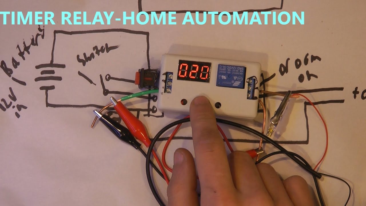
DC 12V 10A Adjustable Time Delay Relay Module LED Digital Timing Relay

How To Make Digital Timer Switch Electrical Wiring Diagram | mechanical

Mechanical Timer TB118 Industrial Time Switch Timer Controller 24 Hours

️12v Timer Wiring Diagram Free Download| Goodimg.co

Wiring 12 Volt Switch
![[DIAGRAM] 12v Wiring Diagram 12 Volt Switches - MYDIAGRAM.ONLINE](https://i2.wp.com/www.oznium.com/images/Rocker-Switch-Connect-_Option-1.jpg)
[DIAGRAM] 12v Wiring Diagram 12 Volt Switches - MYDIAGRAM.ONLINE
Timer Relay Schematic Diagram
